Top View
For the past two years I worked on various projects that used the RFM69 module from Hope RF. This self-contained radio module allowed me to establish wireless links between various sensors and gateways for PIC, Arduino and ESP32 based projects.
One consistent problem that I experienced, was that trying to connect the RFM69 module to a prototype board was difficult. This was because the RFM69 module PAD footprints were not at 2.5mm pitch (which is a standard for most prototype boards). I purchased some PCB carriers from https://modtronicsaustralia.com in the past, which did make this task a little easier.
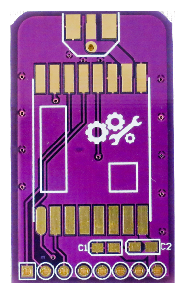
There were two models that I used, and while they worked well for me and many other people, I had a couple of small issues with them. The slim PCB version (seen above) did not have all the PIN’s from the RFM69 available to the user. I did like working with this model as it could plug into one side of the prototype boards or I could connect it via dupont terminals directly to an Arduino or an ESP32.
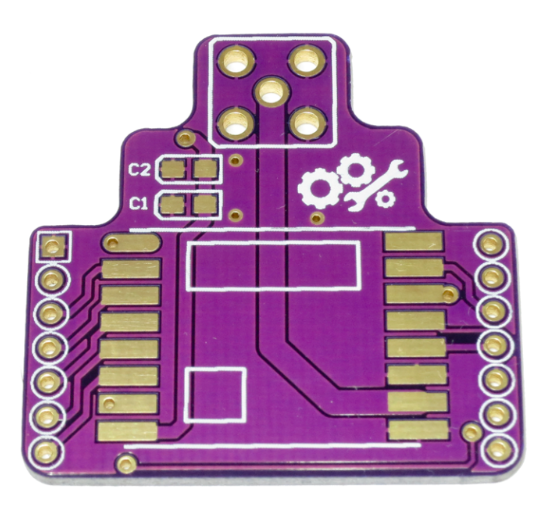
The full size breakout board that I also used did expose all the connections from the RFM69 module. Unfortunately it had one down side: it took up too much space on the prototype board. I looked elsewhere for various carriers or breakout boards for the RFM69 module, but could not find anything that met my requirements. So I decided it was time to tackle this problem myself and ‘scratch my own itch’, as they say in the industry.
My requirements for the breakout board:
- Must connect into a prototype board on any side.
- Have at least 2 I/O pins from RFM69 available.
- Have the other I/O pins available on a separate header.
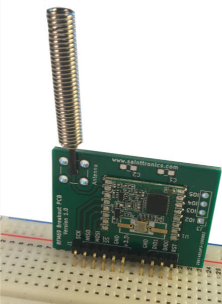
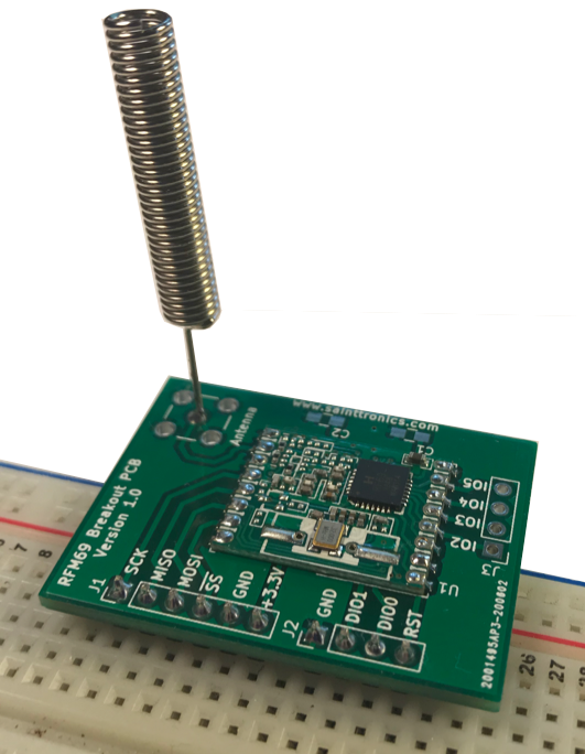
- Be able to mount vertically to save space and horizontally to make prototyping easier.
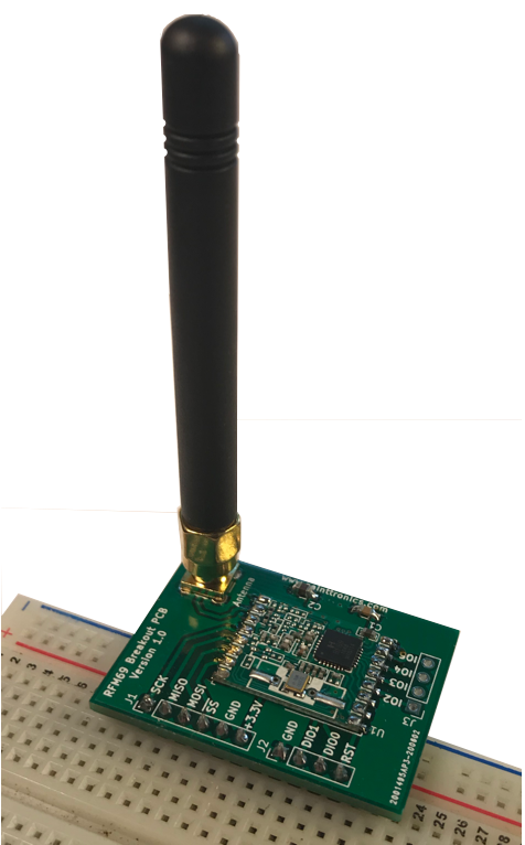
- Support a range of different antenna connections.
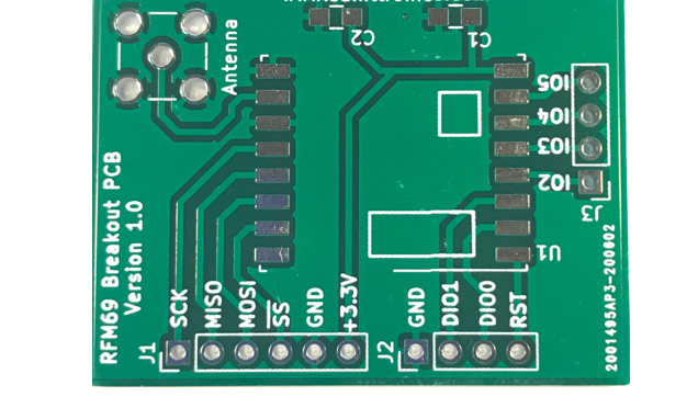
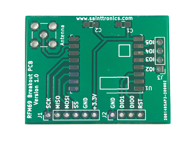
So after testing a couple of designs, I settled on the simple layout that met the requirements above. The board was designed in KiCad 5.0, and after a couple of minor tweaks with one of the design files, I was able to place the order for some of these to be manufactured by JCLPCB.

After a couple of weeks a box of boards arrived on my doorstep. A few days later I had several of these PCBs fitted with some RFM69 modules and operating in some of my current projects with no problems.
The board has been designed so that it can be mounted vertically as well as horizontally. It can also be connected to micro-controllers using flying leads and DuPont connectors. It accommodates a wide range of different antenna configurations.
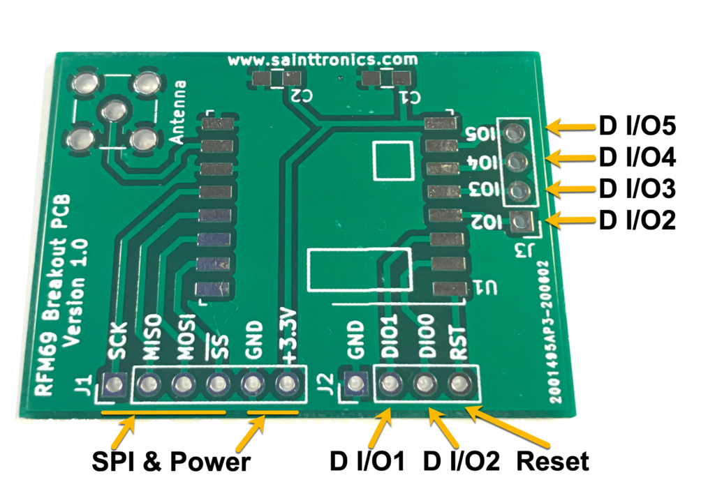
The pin configuration has been set up to keep the important connections in one header, then to allow the connections to be split into two additional headers. This allows the user to decide if they want to use all of the connections or just the ones that are important to them.
I’ve made this PCB available to anyone who wants to purchase one for their projects. This should help other engineers and makers working with the RFM69 in their projects and prototypes. If you have any comments on the PCB or ideas that you would like to see incorporated into possible future revisions, please let me know.
In a future post, I will show you how I use the RFM69 modules with Arduino, ESP32 and PIC16 microcontrollers. I currently use the Platform IO plug-in for Visual Studio Code, and have been very successful in getting these modules operating, after several weeks of frustration with SPI settings, interruptions and a variety of other issues. All of which I will share in a future post.